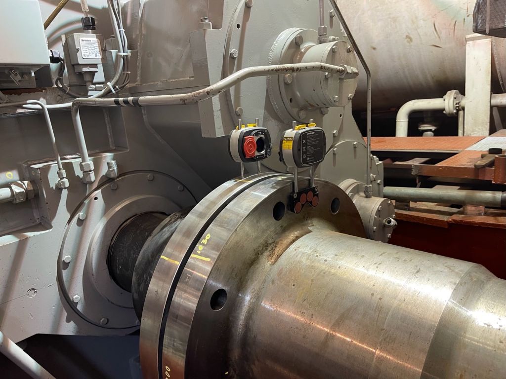
FEM (Finite Element Method) Shaft Modeling refers to the application of numerical simulations using FEM to analyze and optimize the mechanical behavior of shafts used in marine vessels, such as ships, boats, and submarines. This modeling technique is crucial for ensuring the structural integrity, reliability, safety, and efficiency of marine propulsion systems.
At Rotatek, our Field Service Engineers are experts at completing the following:
- GAP & SAG Calculation
- Bearing Loads
- Bearing Misalignment
- Shaft Deflection
Shaft model alignment calculations can be used during the design stage of a vessel to ensure correct alignment or later in the operating stage to correct misalignment of the propulsion system.
how Can we Help you?
Our expert team is ready to help you with your next project. Explore the industries we serve or contact us to learn more.
FEM Shaft Modeling is a valuable tool for marine services, as it aids in designing robust and reliable shafting systems, optimizing fuel efficiency and minimizing the risk of unexpected failures during the operation of marine vessels.
Geometry and Meshing
Geometry and Meshing: FEM Shaft Modeling starts with creating a 3D geometric representation of the shafting system, based on the engineered drawings, including the engine, reduction gear, intermediate shafts (if present), and the propeller shaft. The shafts are discretized into small elements, and a mesh is generated with nodes and elements, just like in the general FEM modeling process.
Boundary Conditions
Boundary conditions are applied to the FEM model to represent the operational scenarios of the marine vessel. These boundary conditions may include rotational constraints at the engine and propeller ends, as well as bearing supports along the shaft’s length to mimic the actual bearing arrangement found in the ship’s structure.
Loads and Forces
In FEM Shaft Modeling for marine services, various loads and forces are considered, including:
- Engine Torque: The torque produced by the ship’s engine is applied at the engine output shaft
- Propeller Thrust: The thrust generated by the propeller is applied at the propeller shaft
- Bearing Loads: The loads experienced by bearings supporting the shaft are considered to ensure their proper functioning and longevity
Solving the Equations
The FEM software solves the set of governing equations for the shafting system iteratively using numerical methods. The software calculates the shaft’s displacements, stresses and deformations at different points along the shaft’s length.
Analysis and Optimization
Rotatek Field Service Engineers use the results from the FEM Shaft Modeling to analyze the shaft’s behavior and advise on optimal shaft alignment.
